
1. Introduction
1.1 The Daily Commute to Work

Suddenly, you realize that you’re already running late, so you rush into the bathroom like a flash, speed wash, get dressed in a hurry, copy your phone with your left hand, pick up the bread with your right hand, and nibble on your breakfast while getting dressed.
At this time, the old problem of commuting is again in front of you: do you want to finish this mouthful of bread, brush your teeth and wash your face, or do you want to rush out the door first to catch the bus?
It’s hard to make a tough decision - put down the bread and rush out the door at a fast pace. You took out your phone and tapped on the familiar Metro Ride App or Bus Metro Ride Code app.
**Then, a QR code lights up on the screen, which is the “knocking brick” for your daily commute. **
You walk quickly to the subway station, the cell phone QR code scanned on the gate, “whoosh” sound, the gate opens, you easily through, no longer need to queue up to buy a ticket, no longer by the morning rush hour congestion disturbing.
You walk into the subway car, squeeze into a corner, take out your cell phone and start planning your day.
1.2 Bus & Subway Ridership System
As mentioned above, people only need a cell phone and a QR code to complete all the matters of commuting to work.
So how is this convenient bus or subway ride system designed? How does the technology and architecture behind it support your daily commute?
Today let’s unveil this modern **city hit workers commuting small can **, in-depth discussion ** ride system design and implementation **.
In this post, Xiao ❤ will take you into the world of ridesharing system to find out how it came out from a science fiction movie and became an integral part of our daily life in just a few years.
2. Requirements Design
2.1 Functional Requirements
Translated with www.DeepL.com/Translator (free version)

- User Registration and Login: Users can register for an account through the mobile app or applet and use the account to log in to the system.
- Route Inquiry: Users can inquire the line and station information of the subway, including departure time, ticket price, etc.
- Get Ride QR Code: The system generates the ride QR code according to the user’s information.
- Get the real-time location of the subway: Users can query the real-time location of the subway and check how long the subway is still arriving from the current platform.
- Ride Scanning and Auto Payment: Users can complete the ride by scanning the QR code when entering and exiting the station, and the system automatically calculates the fare and makes payment based on the mileage of the ride.
- Transaction Record Inquiry: Users can inquire about their transaction history, including ride time, amount, route and other information.
2.2 Non-functional Requirements of Ridesharing System
The user volume of the ride-sharing system is very large, according to the “China’s Major Cities Commuting Detection Report-2023”, the number of people in first-tier cities who take the bus & subway to work every day is generally more than ten million, with an average commuting time of 45-60 minutes, and concentrated in the morning peak and evening peak hours.
Therefore, when designing a ride-sharing system with non-uniform hotspot data distribution and non-uniform crowd distribution, the following points need to be considered:
- User distribution is non-uniform, the users of the ridesharing system in the first-tier cities, exceeding the ordinary cities by several orders of magnitude.
- Uneven distribution of time, the original design of the ride-sharing system is to facilitate commuting to and from work, so the number of users in the morning and evening peaks will be a few orders of magnitude higher than other time periods.
- High Concurrency: Considering that the bus/subway system may be used by a large number of users at the same time during peak hours, the system needs to have high concurrency processing capability.
- High Performance: In order to provide fast query and payment services, the system needs to have high performance and the response time should be as short as possible.
- Scalability: As the number of users increases, the system should be easily scalable to meet future needs.
- Availability: The system needs to guarantee 24/7 availability to provide services at any time.
- Security and Privacy Protection: The system needs to ensure the security and privacy of user data, including the protection of payment information and personal information.
3. Outline Design
3.1 Core Components
Translated with www.DeepL.com/Translator (free version)

- Front-end Application: Develop mobile App and small program, provide user registration, login, query and other functions.
- Backend Service: Design backend service, including user management, route query, QR code management, order processing, payment system and so on.
- Database: Use relational database MySQL cluster to store user information, route information, transaction records and other data.
- Push System: Push the payment result after the ride to the user’s cell phone in both online and offline ways.
- Load Balancing and Message Queuing: Consider using load balancing and message queuing techniques to improve system performance.
3.2 Ride Process
1) Interaction between user’s cell phone and backend system
The interaction timing diagram is as follows:
Translated with www.DeepL.com/Translator (free version)
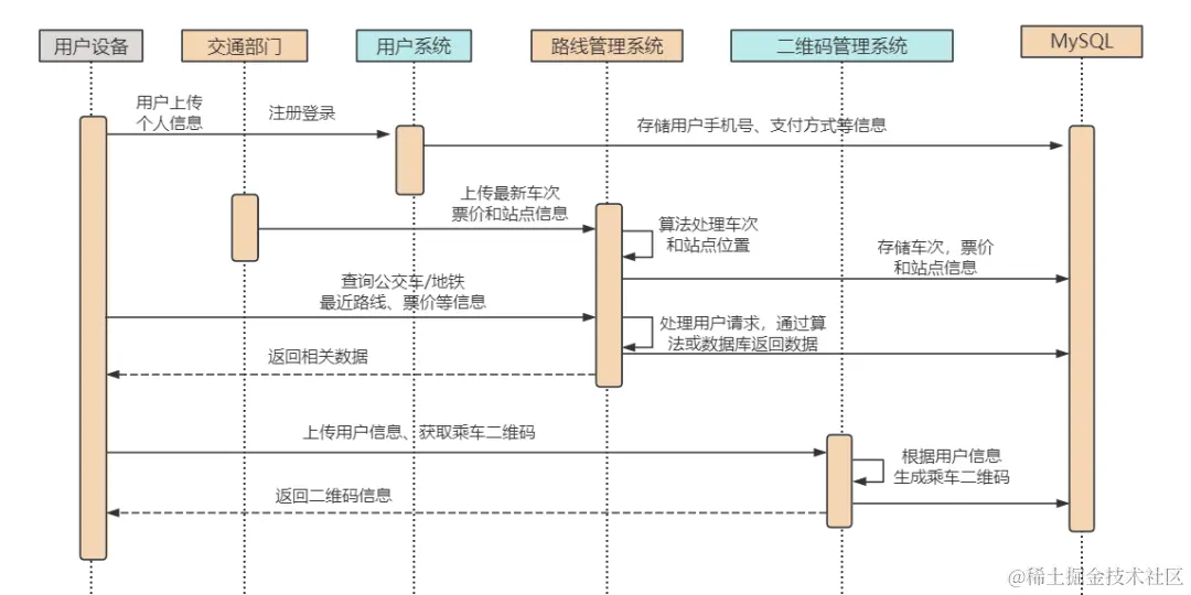
1. User registration and login: Users first need to register on the mobile application and login to the system, providing personal information, including user name, cell phone number, payment method, etc.
2. Querying Ride Information: Users can use the mobile app to query bus/subway routes and fare information, and users can choose the appropriate route according to their travel needs.
3. Generate QR Code for Riding: After the user logs in, the system will generate a QR code for riding, which can be viewed on the user’s cell phone at any time. This QR code is the common ride QR code for urban public transportation system, and at the same time, the code is associated with the user’s account and payment method, and the user can use it to take any bus or subway at any time.
2) Interaction between the user’s phone and the bus
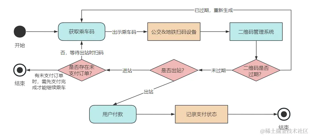
The interaction UML state diagram is as follows:
- **
- User Entry Code Scanning:** When a user enters a subway station, they scan the ride code from their cell phone on the entry device. This device sends the scanned ride code to the backend system.
- Inbound Data Processing: When the backend system receives the inbound information, it verifies the validity of the ride code, checks whether the user has a record of entering the station, and records the time and location of the entry.
- User Outbound Code Scanning: The user scans the ride code on the cell phone on the outbound device after the ride is finished.
- Outbound Data Processing: When the backend system receives the outbound information, it will verify the validity of the ride code, check whether the user has a corresponding inbound record, and record the time and location of the outbound.
3) Processing by the backend system
- Ride Fee Calculation: Based on the user’s inbound and outbound locations and ride rules, the backend system calculates the ride fee. This fee can vary according to different cities and operators.
- Ride Fee Recording and Deduction: The system records the ride fee and deducts the fee from the user’s payment method (e.g., Alipay or WeChat Wallet).
- Ride Record Storage: All ride records, including information on inbound and outbound stops, fees, etc., are stored in the ride record table for users to view and service providers to bill.
- Notification to Users: If necessary, the system can send notifications to users that their rides have been deducted.
- Database Interaction: Throughout the process, the system needs to interact with the database to store and retrieve data such as user information, ride logs, and fare information.
3. Detailed Design
3.1 Database Design
- ** User information table (User)** , including user ID, cell phone number, password, payment method, creation time, etc..
- Table of QR Code (QRCode) , including QR Code ID, User ID, City ID, Generation Time, Validity Period and QR Code Data, etc..
- ** Vehicle & Metro Train Table (Vehicle)**, including vehicle ID, license plate or metro train number, model (bus, metro), scanning device serial number, etc.
- TripRecord (TripRecord), including Record ID, User ID, Vehicle ID, boarding and alighting time, starting and ending stops.
- PaymentRecord (PaymentRecord), including Payment ID, Ride ID, Transaction Time, Transaction Amount, Payment Method, Payment Status and so on.
The above are some of the basic information of the database tables and their fields that need to be designed in the bus & subway ride system, and then according to the specific needs and system size, the table structure and field design can be further optimized to meet the performance and scalability requirements.
Detailed design In addition to designing the table structure, we also discuss for two core issues:
Shortest route query
Ride QR code management
3.2 Shortest route query
According to the bus & subway routes given by the transportation department, we can draw the following station map:

Assuming that there are stations A-F in the figure, the transportation involved in the subway line 1 and 2 buses, the user’s starting point and the end point for the A, F, respectively. We can use Dijkstra’s algorithm to find the shortest path between the two points, the specific steps are:
Steps have traversed the set of untraversed set 1 selected into A, at this time the shortest path A->A = 0, and then A as the middle point, start looking for the next neighboring nodes {B, C, D, E, F}, which is adjacent to A nodes B and C, AB = 6, AC = 3. Next, select the shorter path node C start traversing 2 selected C, A->C = 3, at this time has traversed the set of {A, C}, in order to A and C as the middle point, start to find the next neighboring nodes {B, D, E, F}, where the nodes adjacent to A and C are B and D, AB = 6, ACD = 3 + 4 = 7. Next, select the shorter path node B to start traversing 3 to select B, A -> B = 6, at this time the traversal set has been traversed for {A, C, B}, the neighboring nodes of A have already been traversed to the end, and start to look for nodes {D, E, F} and the nodes adjacent to B and C. nodes {D, E, F}, where the nodes adjacent to B, C are D. Node D already has a distance record (7) before, and now the new optional path is ABD=6+5=11. Obviously the first path is shorter, so the nearest distance 7 of D is added to the set.4 Pick D, A->D=7, at this point the set has been traversed as {A, C, B, D}, and look for the nodes adjacent to D {E , F}, where DE=2, DF=3, select the node E of the nearest path to be added to the set 5 select E, A->E=7+2=9, at this point the set has been traversed as {A, C, B, D, E}, continue to search for the node {F} that is close to D and E, where DF=3, DEF=2+5=7, so that the nearest distance of F is 7+3=10.6 select F, A->F=10, at this point The traversal set is {A, C, B, D, E, F} all nodes have been traversed, from point A, their nearest distances are {A=0, C=3, B=6, D=7, E=9, F=10}
Before the user queries the route, the transportation department inputs the latitude and longitude information of the bus & subway stops into the Route Management System and stores the corresponding stops according to the two-dimensional spatial latitude and longitude encoding.
We set the west longitude to be negative and the south latitude to be negative, so the range of longitude on the earth is [-180, 180] and the range of latitude is [-90, 90]. If we take the prime meridian and equator as the boundary, the earth can be divided into 4 parts.
Based on this principle, we can first encode the two-dimensional spatial latitude and longitude into a string to uniquely identify the location information of the user or site. Then we can use Redis’ GeoHash algorithm to get information about all the sites near the user’s starting point.
The GeoHash algorithm works by converting the latitude and longitude of a location into an address-encoded string that represents a rectangular area, and using this algorithm to quickly find all sites in the same area.
Once the latitude and longitude of the starting location is obtained, the system can call the route management system to find the best bus or subway route based on the information of nearby stations.
Once the user selects a route, the navigation engine launches and provides real-time navigation guidance. The navigation engine may use map data and GPS positioning to guide the user to the starting and ending stops.
3.3 Ride QR Code Management
Ride codes are generated using QR code (Quick Response Code) technology, which can hold more information and represent more types of data than traditional Bar Code barcodes.
The generation of QR codes is very simple, using the Go language as an example, and only requires the introduction of a three-way library:
1 | import "github.com/skip2/go-qrcode" |
The following is a detailed description of the interaction between the user and the system of this function, QR code information storage, and high concurrency request processing:
- User-System Interaction: The user first logs in on the cell phone App, and the system verifies the user’s identity and payment method. Once the verification is successful, the system dynamically generates a QR code based on the user’s identity information and payment method, and this QR code contains the user’s identification information and related ride parameters.
- QR code information storage: The generated QR code information needs to be stored and associated in the background. Usually, this information is stored in a specialized database table that contains the following fields:
- QR Code ID: Primary key ID that uniquely identifies a QR code.
- User ID: Unique identifier of the user associated with the ride code.
- QR Code Data: the content of the QR code, including user information and ride-sharing parameters.
- Generation time: the time stamp of the QR code generation, used for subsequent verification and management.
- Expiration date: The expiration date of the QR code, usually a time limit is set to ensure security.
- High Concurrency Request Handling: In a high concurrency situation, a large number of users will generate and scan the QR code at the same time, so some strategies are needed to handle these requests:
- Load Balancing: The backend system can use load balancing technology to spread the requests to multiple servers to share the load of the servers.
- Cache Optimization: The generation of QR codes is a relatively time-consuming operation. Redis can be used to cache the generated QR codes to avoid repeated generation.
- Limit Frequency: In order to prevent abuse, you can limit the frequency of QR code generation for each user, for example, only 5 times per minute are allowed, which can be realized by limiting the flow.
In conclusion, to generate ride codes through QR code technology, the backend system needs to have the capability of high concurrency processing, including load balancing, caching and frequency limiting strategies to ensure that users can quickly obtain valid ride QR codes.
At the same time, the QR code information needs to be stored and managed securely, e.g., encrypted storage to protect users’ privacy and payment information.
4. Ride-sharing system development
4.1 Other designs
In addition, the positioning and arrival time calculation of bus or subway may involve core components such as positioning devices, GPS system, NoSQL database, user TCP connection management system, etc., and provide users with accurate ride information through the processes of real-time data collection, location processing, arrival time calculation and information pushing.
Meanwhile, auto-payment is also an important function for the convenience of users, which can be realized by integrating with the third-party payment platform.
4.2 Future Development
The future development of bus/subway ridership systems can include the following directions:
- ** Intelligent Riding:** Introduction of intelligent devices, such as automatic face recognition of passengers and face deduction.
- Big Data Analytics: Utilizing big data technology to analyze ridership data and provide better service.
During the design and development process, it is also important to constantly consider user experience, performance and security to ensure that the system can meet the growing demand.
Due to space constraints, this concludes the article.